LX-5020 - Rotating vs. Static Xenon I
Technical Bulletins
Posted 2023
Last Updated 2023
LX-5020
How two different hardware configurations can be used to simulate the same test environment
Abstract
In recent years, almost all major weathering test procedures have been modified from hardware-based to performance-based. These newer test methods have significant benefits. This paper examines how the two different approaches to creating the same test environment affect technical issues like light spectra, irradiance control, filter types, moisture, humidity control, temperature control and calibration. It also addresses practical considerations like sample mounting, maintenance, and general complexity. Finally, the paper reviews data that validates the concept that performance-based test methods can be successful, as long as comparative filter systems and exposure conditions are properly defined and utilized.
Background
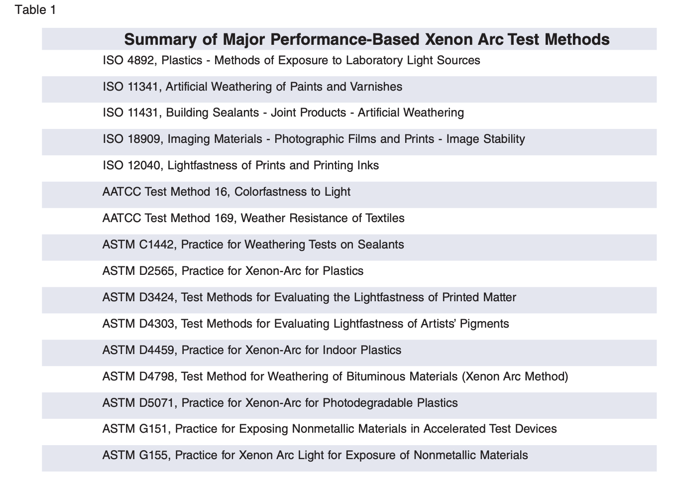
Over the course of the last 10 years, almost all the major weathering test protocols have been updated from hardware-based descriptions of the test apparatus itself (e.g., water-cooled lamp, air-cooled lamp, etc.) into performance-based descriptions of the exposure environment to which the test specimen is exposed (e.g., light spectrum, irradiance, temperature, relative humidity). The old-fashioned hardware-based approach goes back to a time when we lacked the practical technology to accurately measure and control the critical test environment. Since we couldn’t adequately characterize the critical test conditions, we wrote methods that simply described the test apparatus. This approach was based on the hope that, by using the same (or similar) hardware, we could expose test specimens to the same stresses and achieve the same results. More recently, advances in technology have allowed the scientific community to progress forward from the old, arbitrary, hardware-based approach to the new performance-based methods. The performance-based approach is mandated by many organizations like ISO and ASTM. In fact, ISO Directives require that, “whenever possible, requirements shall be expressed in terms of performance rather than design or descriptive characteristics.” In a similar fashion, the American National Standards Institute (ANSI) mandates that standards are to be “performance-based, specifying essential characteristics rather than detailed designs.” These new, performance-based test methods have significant benefits to the end user. They describe the test environment in detail. They allow improvements in technology and control. They encourage competition. The ISO Directives recognize the benefits and state, “This approach leaves maximum freedom to technical development.” A summary of some of the more well-known, performance-based xenon arc weathering test protocols follows (titles have been abbreviated):
Rotating-Drum or Static-Array
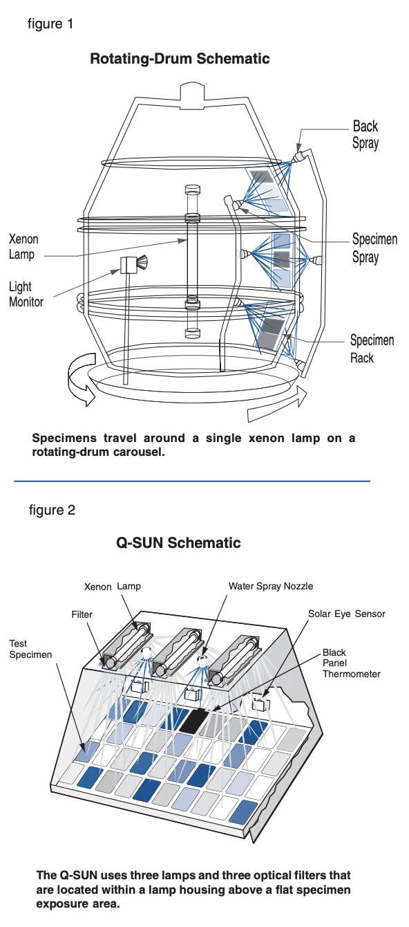
When examining how two different hardware configurations create the same test environment, the most obvious difference between the two approaches is the way in which the test specimens are exposed to the xenon light. One method mounts the specimens on a rotating drum and the other uses a static array. The first rotating-drum light stability testers were developed around 1918 and used a carbon arc as the light source. This device features a central light source or lamp(s), positioned vertically, with a filter system surrounding it. The test specimens are mounted facing the light on a drum which rotates around the central lamp like a carousel. More modern versions have added a number of enhancements, but the basic concept has remained unchanged since the First World War. The most popular xenon arc version of this tester uses a water cooling system for its lamp. For purposes of brevity in this paper, this type of water-cooled xenon arc tester will be referred to as “rotating-drum.” More recent technology features a chamber with one or more air-cooled lamps mounted in the ceiling. In this system, the filters are flat and fitted below the lamps. A reflector system built into the top and sides of the chamber enhances irradiance uniformity. The test specimens are mounted below the lamps on a tray. The tray is slightly tilted to allow for water run-off. These testers are sometimes called "flatarray" or "static-array" testers. The static-array tester referred to in this paper is the Q-SUN Xenon Test Chamber, model Xe-3, or "Q-SUN." Regardless of the hardware configurations used, modern xenon testers typically have systems to control light intensity (irradiance), temperature and relative humidity. See figures 1 and 2.
Light Spectra
Xenon arc test chambers are popular for testing materials and products for light stability and weathering because the spectral output of the xenon arc lamp closely matches the full spectrum of sunlight radiation, including ultraviolet (UV), visible light, and infrared (IR). Any light stability or weathering tester must control the quality of the light in order to achieve accurate and reproducible test results. Changes in light intensity may affect the speed of material deterioration while changes in spectral distribution may affect both speed and type of material degradation. Understanding xenon arc lamp emission is complicated by several variables including filter transmission, irradiance control points, irradiance, intensity and lamp aging. Irradiance control systems affect both the light intensity and the spectrum.
Importance of Optical Filters
Unfiltered xenon arc lamps emit too much short-wave UV radiation to allow useful correlation to natural exposures on the earth’s surface. Consequently, testers employ various types of optical filters to reduce unwanted radiation. The choice of filter should depend on the material tested and its end-use application. Most filter types have the greatest effect on the short wavelength portion of the spectrum. To appreciate the importance of the various filter choices, it is crucial to understand the significance of the short wavelength cut-on. Photochemical degradation is caused by photons of light breaking chemical bonds. To simplify: For each type of chemical bond there is a critical threshold wavelength of light with enough energy to cause a reaction. Light of any wavelength shorter than the threshold can break the bond, but longer wavelengths of light cannot break it – regardless of their intensity (brightness). Therefore, the short wavelength cut-on of a light source is of critical importance. For example, if a particular polymer is only sensitive to UV light below 295 nm (the approximate sunlight cut-on point), it will never experience photochemical deterioration outdoors. If the same polymer is exposed to a laboratory light source that has a spectral cut-on of 280 nm, it will deteriorate. Although light sources that produce shorter wavelengths produce faster tests, there’s a possibility of anomalous results if a tester produces wavelengths not found in the material’s end-use environment.
Comparison of Optical Filter Systems
The Q-SUN Xenon Test Chamber uses one or more pieces of flat filter glass for each of its air-cooled xenon lamps. Water-cooled rotating-drum testers use a different system consisting of cylindrical inner and outer filters that fit around the xenon lamp. There are three general types of filter systems that are commonly used in xenon chambers. In ASTM G155 these filters are designated Daylight, Window Glass, and Extended UV. ISO documents currently use different nomenclature. For the daylight and sunlight through window glass spectra, ISO 11341 (Paints) uses the terms “Method 1” and “Method 2” (respectively). ISO 4892-2 (Plastics) uses the terms “Method A” and “Method B” for the respective spectra. The Extended UV spectrum is specified in a number of SAE methods, but not in ISO standards. The most important way these filters vary is in short-wave UV transmission and spectral cut-on. The varying amounts of short-wave UV can significantly affect the speed and type of degradation. Manufacturers of weathering testers often use their own specific nomenclature for the various filters and filter systems used in their machines.
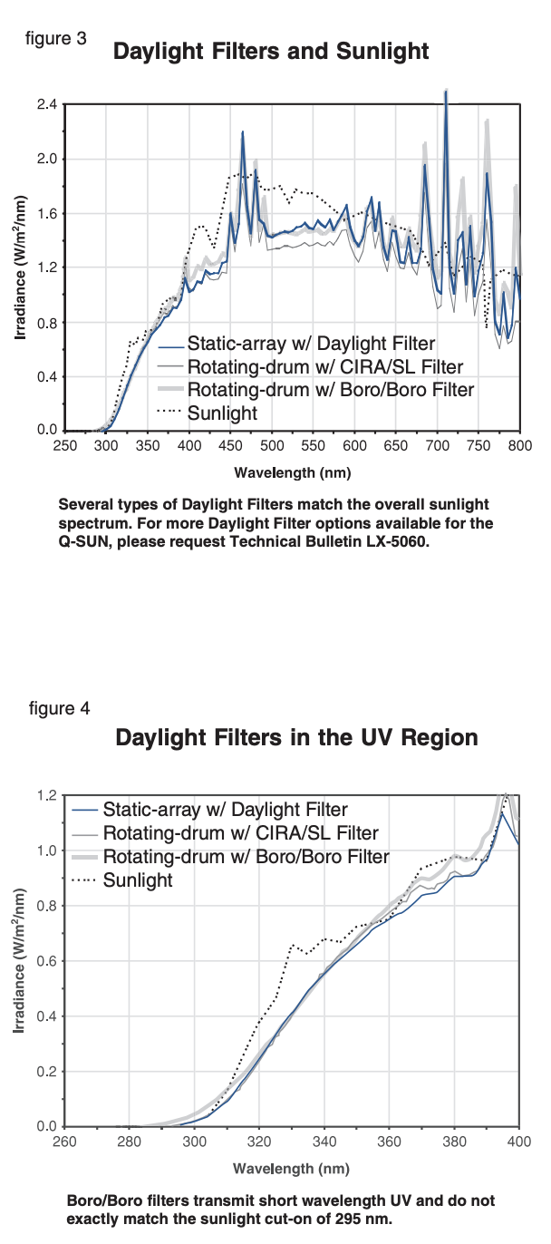
Daylight Filters a r e t h e m o s t commonly used xenon filters and produce a spectrum that compares fairly well to noon, summer sunlight (sometimes called solar maximum).1 The manufacturer of Q-SUN xenon test chambers calls its version of this filter simply a “Daylight Filter.”2 Comparable filter combinations, which also meet the definition of a Daylight Filter, are called “Borosilicate/Borosilicate” (Boro/Boro) and “CIRA/Soda Lime.” The adjacent figures show the spectral power distribution (SPD) of sunlight compared to a xenon arc with the Q-SUN’s Daylight Filter, and a rotating-drum xenon with Boro/Boro and CIRA/Soda Lime filters. As the figure on the top illustrates, both Q-SUN and rotating-drum filters generally match well with the overall sunlight spectrum. However, as the figure on the bottom shows, there are noticeable differences in the shortwave UV region. While both the Q-SUN Daylight Filter and the rotating-drum CIRA/SL filter match sunlight very well, the rotating-drum Boro/Boro filter system has an unrealistically low cut-on wavelength at about 280 nm (much more severe than sunlight’s cut-on of about 295 nm). This means that specimens are exposed to UV of much shorter wavelengths than they would in actual service outdoors. While this may produce faster results, it is not truly realistic, and may lead to correlation problems for some materials.
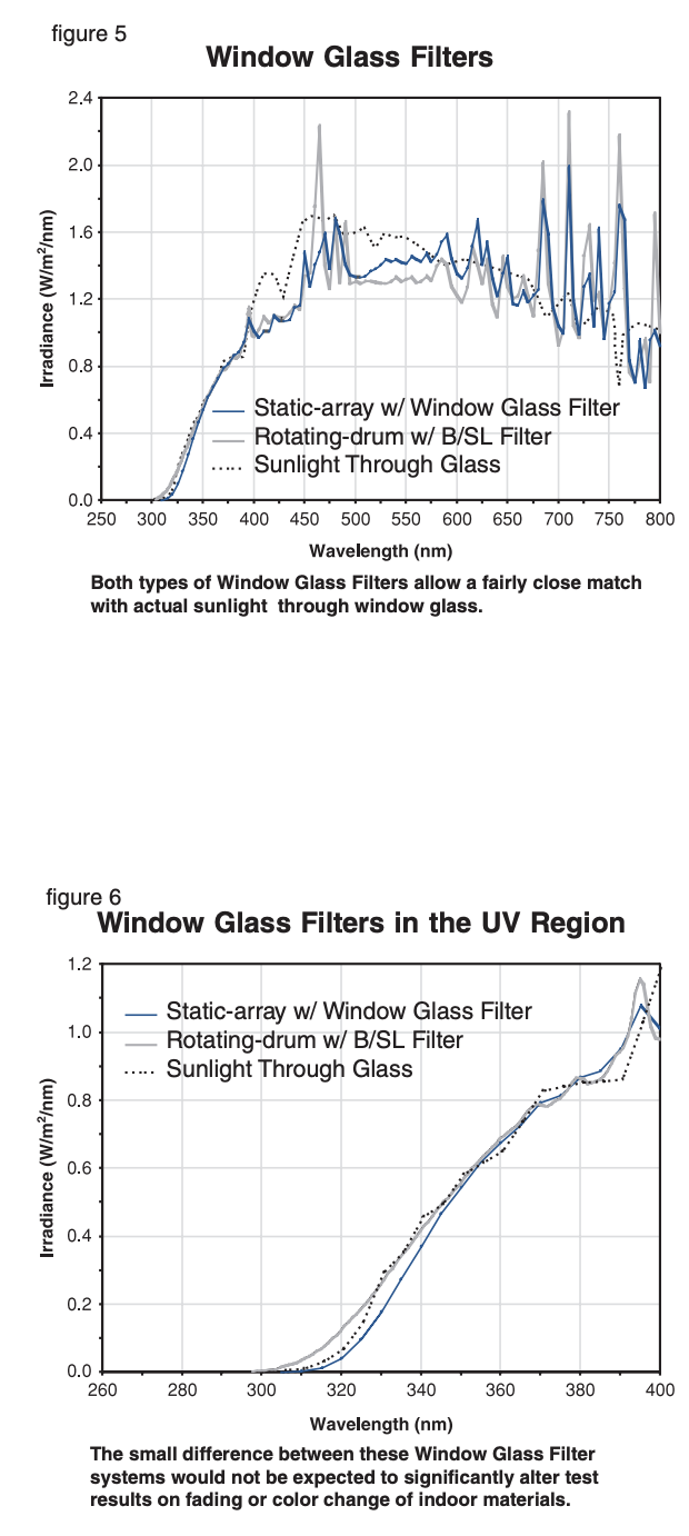
Window Glass Filters are intended to simulate the spectrum of sunlight passing through window glass and are typically used to test products whose primary service life will be indoors. The optical filters used in the Q-SUN are simply called “Window Glass Filters.” Rotating-drum versions of these filters are sold as “Borosilicate/Soda Lime” (also Boro/Soda Lime, Boro/SL, etc.). The figure on top shows a comparative SPD of the Q-SUN and rotating-drum Window Glass Filters, compared to sunlight filtered through window glass. As the figure illustrates, both types of Window Glass Filters allow a fairly close match with actual sunlight through window glass. As the figure on the bottom left demonstrates, the Q-SUN’s Window Glass Filter is a little more realistic in the critical short-wave UV region. This difference may be important for yellowing or physical properties changes in some materials. However, fading and color change are the most common concerns for materials exposed indoors. And, since fading and color change are usually the result of longer wave UV and visible light degradation, this difference would not be expected to significantly alter test results (see Brennan, et al, 2002, for actual exposure test results).
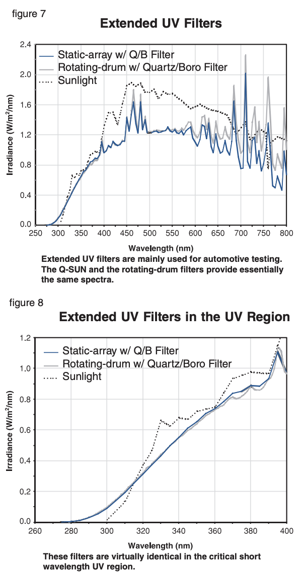
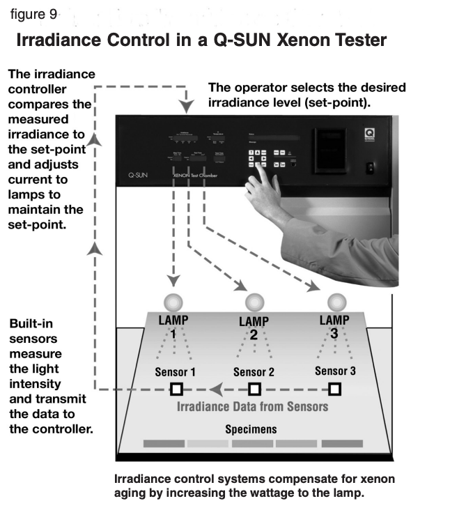
Extended UV Filters are specified in certain automotive test methods that require a more severe spectrum for faster test results. These filters allow very significant short-wave UV, well below the sunlight cut-on of 295 nm. The rotating-drum filter system is known as the “Quartz/Borosilicate” (also Quartz/ Boro). The Q-SUN version is called the “Q/B Filter.” The accompanying SPD figures show how xenon with these filters compares to sunlight. As illustrated, both the Q-SUN and the rotating-drum versions of this filter produce a very similar spectrum, especially in the important short-wave UV region. Both allow significantly unrealistic short wavelength UV as low as 270 nm. These filters would be expected to give equivalent results (see Brennan, et al, 2002, for actual exposure test results).
Filter Solarization is a potential weakness in xenon arc testers. As rotating-drum filters age due to exposure to UV, they lose their ability to transmit the shorter wavelengths of light. This phenomenon is called solarization. The resulting shift in the spectrum can affect the reproducibility of test results. Consequently, rotating-drum filters must be replaced on a frequent basis. The Q-SUN’s filters have been designed not to solarize with extended use. The Q-SUN’s long-lasting filters have been tested for thousands of hours without any significant loss of UV transmission. Therefore, Q-SUN filters do not need to be replaced due to inappropriate solarization. In summary, the main advantage of xenon arc testers is their ability to reproduce the full spectrum of sunlight. As illustrated by the data, the filters used in Q-SUN testers match sunlight and sunlight through window glass as well as, or better than, the filters used in rotating-drum testers.
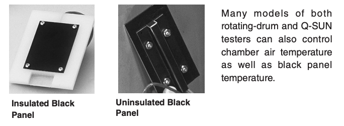
Irradiance Control
Any lamp's output declines with use. To compensate for this, modern xenon arc chambers use a feedback-loop irradiance control system in which the operator presets a desired level of irradiance and irradiance sensors in the chamber measure the light. As the lamp ages and light output drops off, the system automatically compensates by increasing the wattage to the xenon lamp. Although, in theory, xenon lamp intensity could be monitored and controlled anywhere on its spectrum, there are only a few wavelength bands that are commonly used. As a general rule, the irradiance should be controlled in the spectral region where the material is most sensitive (i.e., where degradation is expected to occur). However, the irradiance control point may also differ by industry and/or by application. The 340 nm control point is commonly used for accelerated weathering because the short-wave UV region is often the most damaging to durable products exposed outdoors. Controlling at 340 nm requires a UV sensor equipped with an optical filter that admits only UV in a narrow band centered at 340 nm. Generally, this is a good control point for coatings, plastics, roofing, etc. The most common irradiance intensity levels for outdoor simulations are 0.35 or 0.55 W/m2 /nm @ 340 nm. The 420 nm control point is typically used for indoor light stability applications with Window Glass Filters. Controlling at 420 nm requires a UV sensor equipped with an optical filter that admits only UV in a narrow band centered at 420 nm. This system is normally used when testing materials that are primarily damaged by longer wave UV and visible light, such as dyes and pigments in textiles, papers, and inks. The most common irradiance set-point for indoor simulations is 1.10 W/ m 2 /nm @ 420 nm. Both the Q-SUN and the rotating-drum testers are typically equipped with either a 340 nm or a 420 nm narrow band irradiance control system. Certain European chambers were developed to use a wide band TUV (total ultraviolet, 300 nm to 400 nm), or an extremely wide band total irradiance sensor (280 nm to 800 nm), depending on the specific model. By their very nature, wide band sensors are not as responsive to relatively small changes in the UV. This insensitivity can be an issue when the critical degradation mechanism is driven by the short-wave UV portion of the spectrum. In summary, both the Q-SUN and the rotatingdrum testers have effective, equivalent feedback-loop irradiance control systems. Following recommended lamp replacement schedules will reduce the effects of lamp aging. By using sensors that control the irradiance at either 340 nm or 420 nm, the amount of spectral change in a particular area is further minimized.
Moisture
Both the Q-SUN and rotating-drum xenon chambers simulate the effects of outdoor moisture by spraying water onto the test specimens. In the Q-SUN, test specimens are mounted on a flat specimen tray which is tilted at 5o from horizontal. The Q-SUN’s water spray covers the specimens uniformly and, because of the near horizontal position of the specimens, the water does not quickly run off. In the Q-SUN, specimens stay wet during the entire moisture cycle. Rotating-drum testers have a spray bar and nozzles which spray the specimens with water as they rotate past it. Specimens are wetted for approximately 3 seconds out of each 1 minute revolution. Some testers are equipped with 2 bars to spray both the front and the back of the specimen simultaneously. Because of the vertical position of the specimens, the water quickly runs off the surface. Between these wettings, it is possible for the specimens to dry off as they rotate away from the spray.
Relative Humidity Control
For many materials, control of relative humidity (RH) is considered critical and many test methods require its use. Both rotating-drum xenons and Q-SUN testers can be equipped with RH control. Precise control of RH is difficult because of the high volume of air which must constantly be moved through the chamber to maintain the exposure temperature. To control relative humidity, chamber air temperature must be monitored and controlled. The accompanying figures illustrate the performance of the Q-SUN’s RH control, chamber air temperature and black panel temperature controls. The Q-SUN’s precision RH control system (patent pending) exceeds the requirements of ISO, ASTM, AATCC and SAE test methods, and is superior to the systems used in most of the rotatingdrum testers in the field.

Temperature Control
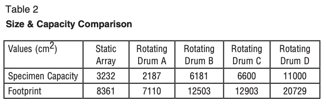
Control of temperature is a critical, but often overlooked, test parameter. Both the rotating-drum and Q-SUN testers typically control the test environment by controlling black panel temperature. The Black Panel Sensor is simply a black coated metal panel with a temperature sensing element attached to the surface. These are sometimes called “Uninsulated Black Panels.” Insulated Black Panels (called “Black Standard” in ISO standards) are also available for both testers. These are made with an insulating plastic base and typically read 5-10oC hotter than the Uninsulated Black Panel.
Practical Considerations
In order to be useful, it is expected that a tester can provide the required exposure environment. However, there are additional practical considerations in the choice of a xenon arc chamber. After all, if a tester is too difficult to use, or too expensive to purchase, operate, or maintain, it will not be useful, no matter how advanced the technology.
Capacity & Footprint. The Q-SUN tester has a compact size, while still allowing a large area for test specimens. It has an exposure area of 501 in2 (3232 cm2). This is almost 50% more exposure area the rotating-drum testers with a similar “footprint.” See Table 2.
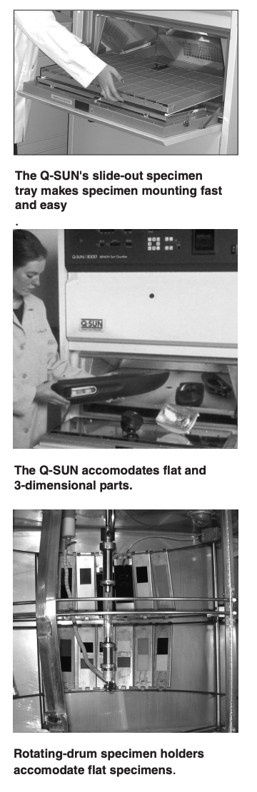
Sample Mounting. The Q-SUN’s slide-out specimen tray allows faster, easier, and more flexible specimen mounting than the rotating-drum. The tray can accommodate different sizes of flat panels or three-dimensional specimens like parts, components, bottles, and test tubes. The flat tray is also useful for testing materials that flow at elevated temperatures, for exposing substances exposed in petri dishes, and for ponding in roofing applications. Rotating-drum testers can only mount flat panels in a vertical position. Specimens must be clipped into special holders to be hung on the exposure rack.
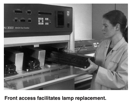
Maintenance. The Q-SUN Xenon Test Chamber was designed for easy maintenance. All normal maintenance is performed from the front of the unit. Lamps are easy to access and to replace. Q-SUN filters do not need replacement. With the rotating-drum chambers, water-cooled lamps and filters are inconveniently located. Test specimens must be removed for regularly scheduled lamp and filter replacement.
Air-cooled vs. Water-cooled Lamps
In addition to light, xenon arc lamps produce a lot of heat from visible and IR emissions. This creates certain challenges for operation and maintenance. The Q-SUN removes excess heat by moving large volumes of air through the lamp housing. This simple, inexpensive function is known as air-cooling.
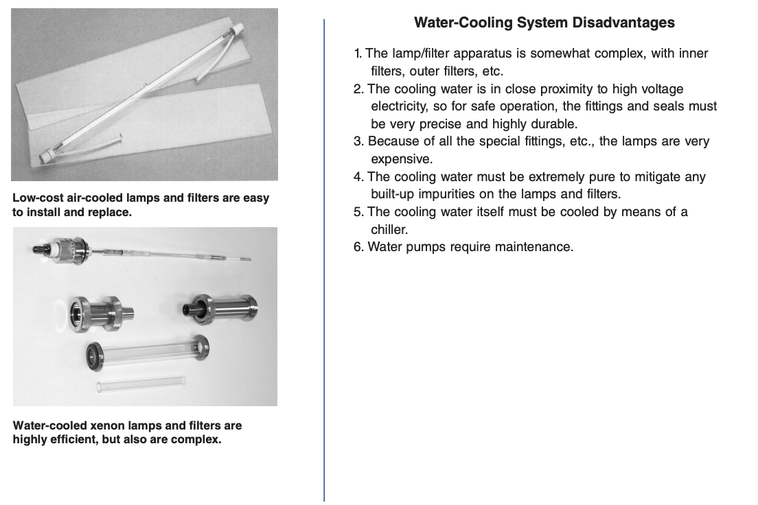
The rotating-drum uses a water-cooled lamp system. Because water is an excellent heat transfer agent, this is highly efficient. Consequently, the rotating-drum lamps can be operated at a very high wattage to produce high irradiance. However, the water-cooling system has a number of disadvantages.
Irradiance Calibration
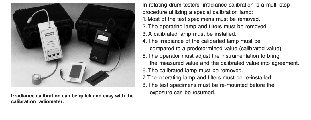
The Q-SUN irradiance calibration system utilizes a radiometer. To calibrate the Q-SUN’s sensors, the radiometer’s sensing element is placed in the mounting tray in the same position as a typical test specimen. Its data transfer cable is plugged into the calibration port on the front of the instrument panel. Calibration is accomplished with a key stroke as the radiometer measures the lamp output and sends a signal to the on-board control system, which automatically adjusts the calibration accordingly.2 There is no opportunity for human error in transcribing or transposing numbers. Lamps and filters all stay in place during the procedure, which takes only a few minutes to perform.
Summary & Conclusions
This paper has illustrated that all the critical test parameters including light spectrum, light intensity (irradiance), chamber air temperature, black panel temperature, and relative humidity can be controlled and reproduced in testers which employ significantly different hardware configurations. The new, performance-based test methods have significant benefits to industry. They describe the exposure environment in detail. They open up the field of lab weathering to improvements in technology and control. They allow the user a new flexibility to choose between a number of different models of xenon test chambers, produced by various manufacturers. Appendix 1 is an example of results from a comparison test between the rotating-drum and the Q-SUN xenon test chambers.
Appendix 1
Similarity of Results Between Lab Weathering Testers
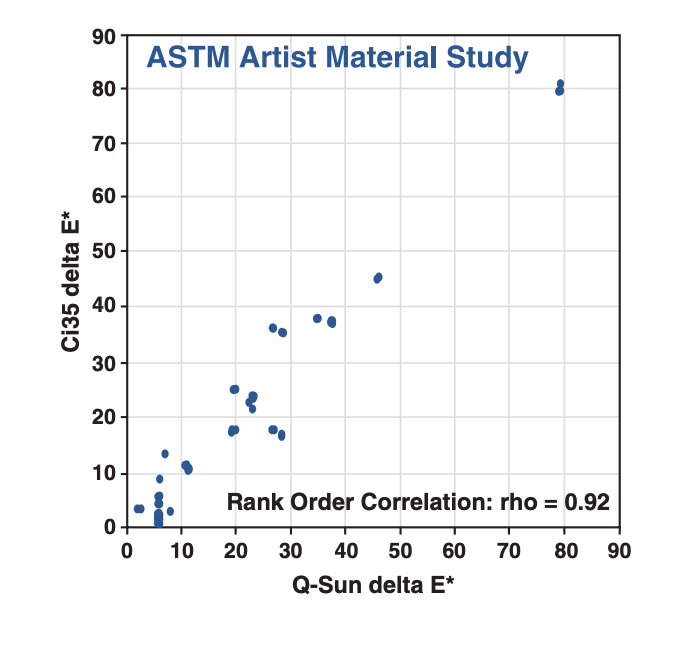
Studies performed by the ASTM Committee G03 on Weathering and Durability compared the consistency of results from various models of water-cooled rotating-drum xenon testers produced by a single manufacturer. The study found that there was excellent agreement between results when materials were “evaluated in terms of performance ranking compared to other materials or to a control” (ASTM G151). However, “different laboratories using identical test devices and exposure cycles showed significant variability” in the absolute values obtained (quoted from ASTM G151 precision and bias statement). For a detailed examination of these and related results, consult a series of papers by Fischer and Ketola (1993-1995). A more recent paper documents the results from a series of comparison tests between rotating-drum and Q-SUN testers. These tests investigated a number of very different types of test specimens ranging from textiles, to paints, to plastics.3 Typical of the comparison tests was one which studied the light stability of various artists’ colors which were exposed in several different models of xenon arc. As shown below, there was excellent agreement between the different devices. In general, “the results indicate that the concept of performance-based test protocols can be successful, as long as comparative filter systems and exposure conditions are properly defined and utilized.”
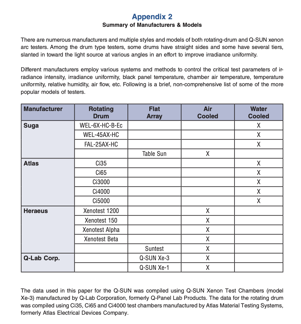
Appendix 3
A Note on Light Measurement
A spectroradiometer was used for all measurements. Q-SUN measurements were taken in the Q-SUN/xe-3. Rotating-drum measurements were taken in multiple Ci35, Ci65 and Ci4000 testers in several different labs. Irradiance was measured at every 1 nanometer (nm) in the UV and every 5 nm in the visible region. The resulting Spectral Power Distribution (SPD) curves are plotted as graphs of irradiance versus wavelength. Measurements were taken with the sensor in the same position as an ordinary test specimen, so that the irradiance measured would be the same as a specimen receives. All measurements were taken with the same instrument to ensure that the various data would be strictly comparable. (Comparisons of SPDs generated by different spectroradiometers can lead to confusion, because of differences in input optics, wavelength bandpasses, and limitations in the state-of-the-art in spectral irradiance calibrations of UV sources.) The instrument used was an International Light IL 700 Spectroradiometer, No. 504, consisting of the following components as shown below: Input Optics: Teflon cosine diffuser for wide viewing angle Monochromater: Kratos GM-200, double grating monochromator with calibrated 1.0 nanometer band pass, stray light less than 1 part per million Detector: PM 270C Photo-multiplier, with an S-5 response, operated from an IL 760 power supply Picoammeter: IL 700A Radiometer Calibration: Watts per meter per nanometer, traceable to the US NIST, Calibration Certificate No. 404045901.