LC-0871 The QCT Condensation Tester: Why It Works
Technical Bulletins
Posted 2023
Last Updated 2023
LC-0871
There are quite a number of laboratory methods for accelerated simulation of the damage caused by rain and dew on metals and organics. However, the old fashioned methods of water immersion, high humidity, fog, or salt spray are not entirely satisfactory. They do not accurately reproduce outdoor conditions because they are not designed to produce and control the essential feature of outdoor wet - ness attack - condensation. In contrast, the QCT ® condensation tester is a more realistic simulation because it produces a controlled condensation exposure.
The Basic Design
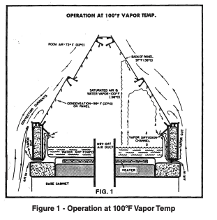
The QCT machine is based on the Cleveland Condensing Humidity Cabinet, originally designed and tested by the Cleveland Society for Paint Technology. With this design, the QCT tester simulates rain and dew by condensing liquid water directly on the test specimen (figure 1). This is achieved by heating the water in the bottom of the test chamber to generate hot vapor. The vapor fills the test chamber, and creates 100% humidity at a temperature setting of anywhere from 40°-80°C (100°-180°F). Because the test panels are the actual roof of the chamber, room air on the top side cools the panels a couple of degrees below the vapor temperature. This temperature difference in turn causes the vapor to condense as pure liquid water on the under side of the panels. (The whole process is very much like a still). There are important reasons why this method of condensation is the best way to simulate natural wetness exposure.
Not Just a Humidity Cabinet
We go to a lot of trouble to convince people to call our QCT unit a "condensation tester" instead of a '"humidity tester". The difference is not just semantic; it represents a fundamentally different approach to corrosion testing.
Humidity - water in the vapor phase - does not cause corrosion. It's only when water vapor condenses as a liquid that it begins to attack coatings, metals, and rustinhibitors. Also, remember that even at 100% relative humidity, liquid water will not condense on an object unless the object is cooler than the surrounding vapor. In a conventional humidity cabinet, the test samples are completely inside the cabinet, so there is no fool - proof method of cooling the samples to provide reliable condensation. Whatever cooling (and condensation) occurs is a result of uncontrolled cycling of the cabinet's thermostat, or opening of the cabinet by the operator, or other unquantified variables.
In contrast, the design of the QCT condensation tester provides positive sample cooling by room air, so that there is a continuous and predictable supply of freshly condensed water on the sample. For this reason the QCT tester is not a "humidity cabinet", but a "condensation cabinet". It uses 100% humidity only as a means to create liquid condensation.
Outdoor Wetness from Rain and Dew - A Condensation Process
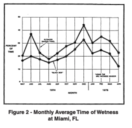
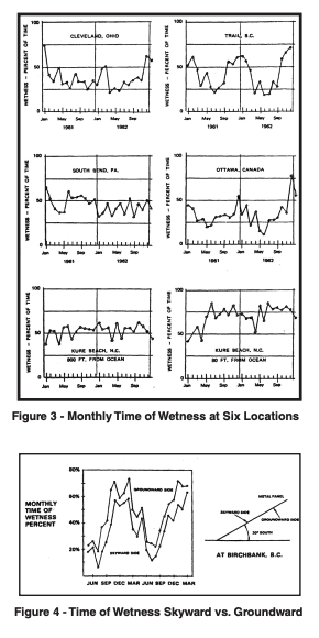
It is not generally understood that, even inland, materials are wet a remarkably high percentage of the time. Figure 2 shows the incidence of liquid water on samples at a Florida test site, as measured by a galvanic detector (Appendix A) which generates a voltage when liquid water is present (1). Figure 3 shows similar wetness measurements at six other locations around North America (2). The data shows that the samples were wet about 30% of the time. That means that materials exposed outdoors average eight hours of wetness per day, or about 2900 hours of wetness per year. This startlingly high incidence of wetness has important implications.
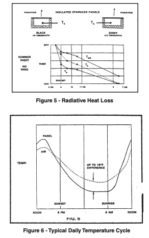
First of all, the incidence of rain is such that it can only account for a small fraction of these hours of wetness. This means that the predominant source of wetness is dew, or condensation, and that materials are wet from dew more frequently and for longer durations than is commonly supposed. Figure 4 further corroborates the predominance of dew over rain, by demonstrating that the groundward side of a test panel facing 30° south is wet more than the skyward side (3).
There is a simple physical mechanism which explains this large accumulation of dew. In order to condense dew, a material must be cooler than the surrounding air. More specifically, it must be below the dewpoint of the air. The way that materials get this cold is by losing heat through radiation to the night sky. Radiative heat transfer is proportional to the 4th power of the temperature difference. Since the night sky is essentially absolute zero, radiation is a powerful cooling mechanism. The rapid effect of radiative heat loss after sundown is shown in Figure 5. Note that the black panel, because of its higher emissivity, loses heat faster than the shiny panel. Figure 6 shows the typical daily temperature cycle caused by this effect.
The fact that radiative cooling is responsible for dew has a number of interesting implications. If the material is "looking" not at the cold sky but at a relatively warm object such as clouds, there will be no radiative heat transfer and no dew. Examples of this are the fact that frost doesn't occur on cloudy nights, and a car under a carport will stay dry while a nearby car in the driveway will collect dew.
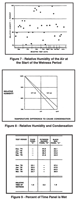
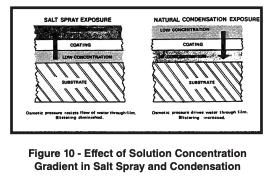
Other effects can also aid or hinder radiation in creating dew. As the relative humidity rises, the dewpoint temperature rises, so not as much cooling is needed to put the material below the dewpoint. This aids dew formation but by no means assures it. And, contrary to common supposition, relative humidity is not a good measure of wetness (Figure 7). High humidity cannot in itself cause dew to condense if there is no radiative heat loss (Figure 8) (4)
Extraneous sources of heat gain also affect dew formation. Wind inhibits the condensation of dew by increasing convective heat gain. With a strong enough wind, convective heat gain will cause the material to assume the temperature of the air, and no condensation can occur. For similar reasons, a test sample with plywood backing is apt to be wet twice as long as a sample with no insulating backing (see Figure 9) (1). At night, the unbacked sample loses heat by radiation to the sky, but it gains heat by convection from the air and by radiation from the ground. The backed sample radiates the same amount of heat to the sky, but because its back is insulated, it gains less heat from convection and from ground radiation. The net effect is that an insulated sample gets cold faster, and hence wet faster.
The fact that materials are exposed primarily to dew, and not rain, affects the type of degradation that will occur. For one thing, dew is saturated with oxygen. It is often the case that water is not destructive in itself, but that water causes damage by bringing oxygen into intimate contact with the material and thereby promoting oxidation. Any attempt to simulate outdoor wetness must insure that the water is fully and reliably saturated with oxygen. The only way to do this is with condensation. The alternate methods of sprays, "fogs", and immersion all fail to control oxygen saturation.
It's also important to remember that when dew condenses, it is pure distilled water, with no dissolved solids. The QCT tester's method of condensing water directly on the specimen duplicates this purity. Other test methods, such as immersion or salt fog, are poor simulations of this aspect of outdoor wetness. And with tests that spray water, even distilled water, it is very difficult to completely eliminate dissolved solids.
The fact that dew lies on materials for many hours at a time is also of crucial significance. This allows the water to penetrate deep within the material to cause internal oxidation. It also allows time for soluble additives to be leached from the material. And in the case of paint films, it gives the water time to permeate through the coating and dissolve solubles between the coating and the substrate. This creates an osmotic cell (5). with the coating as the membrane. The pure condensed dew is the dilute solution, and the water between the substrate and coatings is the concentrated solution (see Figure 10). The resulting osmotic pressure literally pumps water through the coating, causing blistering and lifting of the coating.
Note that in salt fog exposure, the concentrated solution is on the outside of the coating, so the osmotic gradient acts to prevent water from permeating the coating. Salt fog thus reverses the conditions found in natural dew exposure.
Temperature Accelerates Condensation
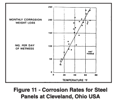
Finally, the fact that materials spend such a large proportion of their outdoor life wet puts a special burden on accelerated tests. With outdoor materials wet eight hours a day, it is virtually impossible to accelerate condensation damage by increasing the number of hours of wetness. Some other means must be used. The QCT machine accelerates by increasing the temperature of wetness to 40°-60°C (104°-140°F). This preserves the essential features of pure condensed dew, while providing a high degree of acceleration. It is not uncomrnon to find that a 10% increase in condensation temperature results in a doubling of the rate of deterioration (see Figure 11) (2). To accelerate outdoor wetness, you need both long periods of wetness and elevated temperatures. And unless you carefully control the temperature of wetness, you don't have control of the acceleration rate.
Appendix A: Time of Wetness Meter
The Time of Wetness Meter (T.O.W. Meter) used to collect the data here, was originally developed by the National Research Council of Canada. Several ASTM committees have subsequently been investigating the meter. The T.O.W. sensor (Figure 12) consists of a zinc plate with two platinum electrodes glued to its face. The platinum is spaced about .1 mm from the zinc with an insulating adhesive. Electrical leads are attached to the two dissimilar metals. When liquid water bridges the space between the two metals, we have a zinc/platinum battery which generates up to 1 volt. When the voltage goes over .2 volts, a running time meter is activated to record wetness time. The platinum/zinc interface is 53 cm (21 inches) in length, and the electrical circuitry is such that .02 microamps is the current flow once the wetness interval is started.
It is important to note that this is a new and different method for measuring wetness. Other "wetness" detectors in use have a wick measuring electrical conductivity changes in response to relative humidity changes in the air. Although humidity might correlate with wetness, such detectors do not give an actual direct reading of wetness on the test surface. However, the zinc/platinum sensor does tell us when there is an actual liquid electrolyte present at the interface of the two metals.
Recent research on the T.O.W. meter has concentrated on the development of a copper/gold sensor to replace the zinc/platinum cell. The new copper/gold sensor is manufactured by the same process as ordinary printed circuit boards. This process should produce sensors that are smaller, easier to standardize, and much cheaper. Otherwise the copper/gold sensor works like the zinc/platinum sensor.
References
Grossman, P.R., "Investigation of Atmospheric Exposure Factors that Determine Time-of-Wetness of Outdoor Structures," Atmospheric Factors Affecting the Corrosion of Engineering Materials, ASTM STP 646, Coburn, S.K., Ed., American Society for Testing and Materials. 1978, pp. 516.
Guttman, H., and Sereda, P.J., "Measurement of Atmospheric Factors Affecting the Corrosion of metals" Metal Corrosion in the Atmosphere, ASTM STP 435, American Society for Testing and Materials, 1968, pp. 326-359.
Sereda, P.J., "Measurement of Surface Moisture , Progress Report", ASTM Bulletin, No. 228, 1968, pp. 53-55.
Heating, Ventilation, Air Conditioning Guide 1958, American Society of Heating and Ventilating Engineers, 1958, p. 177.
McSweeney, E.E., "Water and Metals", Official Digest of the Federation of Societies for Paint Technology, Vol. 37. No. 485, 1965.