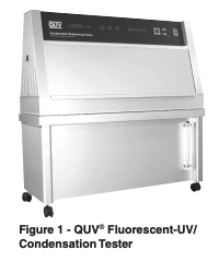
LU-8032 Irradiance Control In Fluorescent UV Exposure Testers
Technical Bulletins
Posted 2023
Last Updated 2023
LU-8032
Reference
Brennan, P. J., Fedor, G. R., “Irradiance Control In Fluorescent UV Exposure Testers,” Accelerated and Outdoor Durability Testing of Organic Materials, ASTM STP 1202, Warren D. Ketola, and Douglas Grossman, Eds., American Society for Testing and Materials, Philadelphia, 1993.
Abstract
Variation in ultraviolet (UV) irradiance is one of the prime causes of variability in tests that use UV lamps to simulate sunlight degradation of polymers. Control of irradiance in ASTM G53 fluorescent UV tests previously consisted mainly of periodic replacement and rotation of aging lamps. A newly developed electronic irradiance control system was evaluated for its effectiveness in controlling UV variation caused by; (1) lamp aging, (2) lot-to-lot variation in lamps, (3) test temperature, and (4) room temperature. In addition, a system of UV baffles and multiple sensors was examined for its effective - ness in reducing variation in UV intensity at different points in the test specimen plane.
Keywords
Accelerated weathering, irradiance, spectral power distribution, fluorescent lamp, ASTM G53, QUV, ultraviolet radiation ASTM G53 is the Standard Practice for Operating Light and Water Exposure Ap - paratus (Fluorescent UV-Condensation Type) for Exposure of Non-metalic Materials [1]. G53 is under the jurisdiction of Committee G03, Durability of Nonmetalic Materials. G53 describes a procedure and equipment used in laboratory simulations of the deterioration caused by sunlight, rain and dew on various materials.
In G53, test specimens are repetitively exposed to alternating cycles of UV light and condensing moisture at controlled temperatures. Exposure conditions can be varied by the selection of the fluorescent UV lamp, the timing of the UV and condensation exposures and the temperatures of the exposures. G53 is widely used to test paints, plastics, roofing, textiles and other materials that would normally be exposed outdoors.
Subcommittee G03.03 has conducted a series of Round Robin exposures to determine the precision of the various “accelerated weathering” test devices described in G03 Practices. All of these devices, including G53, exhibited significant variability in test results. Similar results have been published by Fischer and Ketola [ 2]. This paper describes a series of modifications to the basic apparatus described in G53. These modifications are intended to reduce the variability in test results that are caused by variations in irradiance (i.e., the intensity of the light, as measured in the test sample mounting plane). Control of irradiance in any laboratory tester is important because changes in light intensity usually affect the speed of a material’s deterioration. Changes in a light source’s Spectral Power Distribution (SPD) may affect not only the speed, but also the type of material degradation.
Factors Influencing the Variability in Irradiance
In a G53 device, the light intensity to which a sample is exposed is influenced by several factors:
- Lot to lot differences in lamp intensity, due to limitations in current lamp manufacturing technology.
- Loss of light intensity caused by “aging” of the lamps.
- Differences in light emission due to differences in laboratory ambient temperatures.
- Procedural errors, including lamp rotation, temperature calibration, machine maintenance, and test sample rotation.
A new automatic irradiance control system has been developed by Q-Lab Corporation to address each of these sources of variability. This system is being marketed under the name “Solar Eye.” The system consists of a programmable controller that continuously monitors the UV intensity via four sensors mounted in the test sample plane. A four channel feedback loop system maintains the programmed irradiance level by adjusting power to UV lamps. The irradiance level can be adjusted to varying intensities for different applications. Figure 1 shows a simplified schematic of how the irradiance control system works.
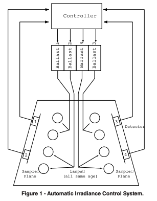
This four channel system differs from previous G53 feedback loop systems in that there are four sensors. Each sensor monitors the intensity of two lamps. Each sensor is individually calibrated by the operator on a regular basis. Other existing systems have no user calibration capability. The calibration is traceable to the National Institute of Standards and Technology (NIST).
In addition to the electronic controller/sensor system, several changes have been made to the test chamber interior. Taken together, these changes greatly reduce the major sources of UV variability that may result in poor reproducibility in test results.
Following is a detailed description of each of the sources of UV variability and how the irradiance control system reduces that variability.
Lot-to-Lot Variability in Lamps. Most of the fluorescent UV lamps that are used in G53 devices are manufactured specifically for accelerated weathering applications. Because of limitations in the ability of suppliers to control glass transmission, phosphor quality and phosphor thickness, the output of these fluorescent UV lamps varies approximately ± 10% between different production runs. For lamps that are not specifically manufactured for G53 applications, the differences between different production lots of lamps is often greater. Automatic irradiance control compensates for lot to lot variations by increasing power to low output lamps and decreasing power to high output lamps. The irradiance level is therefore constant, regardless of lamp efficiency.
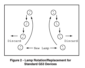
Lamp Aging. The output of any light source declines with use. In standard G53 devices the operator compensates for this by regularly replacing and rotating the lamps. Each tester uses eight lamps, four on each side. Every 400 to 450 hours the oldest lamp on each side is replaced. At that time the remaining six lamps are rotated as shown in Figure 2. This insures that, at any point in time, the irradiance is an average of lamps at four different points on the age/output curve. Depending on the specific lamp type utilized, the average remains more or less stable over time. Lamp life in a standard G53 device is 1,600 to 1,800 hours.
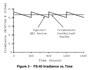
Between the rotation/replacement sequences, lamps with good aging characteristics will decline in output by about 5%. Lamps with poor aging characteristics, such as the North American Philips (NAP) FS-40 lamps, will decline as much as 15% [3]. In other words, the output of a standard tester is at its peak immediately after the lamps are rotated. Over the course of the next 400 to 450 light hours, the light output declines until the lamps are again rotated and two new lamps are added. At that time, the intensity jumps back up as shown in Figure 3.
With feedback loop irradiance control, the tester maintains a constant irradiance level. It compensates for lamp aging by increasing power to the lamps. Lamps are replaced only when they can no longer maintain the programmed set point. Usable lamp life can be expected to be 5 times greater than that in a standard G53 device.
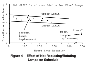
Improper lamp rotation/replacement procedures greatly aggravate the decline in irradiance caused by lamp aging. In the course of establishing the requirements of SAE J2020 [4] (an automotive test method based on G53), hundreds of irradiance measurements were taken in dozens of G53 devices in several laboratories. Figure 4, adapted from J2020, shows some of the measurements taken in properly maintained testers and some taken in poorly maintained testers. The poorly maintained testers were running exposure tests to comply with SAE J2020 but the irradiance level was less than one-half the required level.
Another important consideration in lamp aging, besides the loss in output, is the change in spectral distribution. Figure 5 shows the spectral power distribution of (NAP) FS-40 lamps measured in a G53 device just before and just after lamp rotation. Although the output changes, the spectral distribution does not. The shapes of the two curves remain the same. This is a significant advantage fluorescent lamps have over other types of lamps. Figure 5 showed that the spectral distribution does not change during the standard G53 400 hour replacement/rotation cycle. In the irradiance control system, lamps are replaced only when they can no longer maintain the desired set point. This greatly extends the useful lamp life.
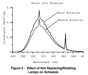
Figure 6 shows the SPD of two sets of QFS-40 lamps measured in a controlled irradiance tester. One set of lamps was aged only 2 hours and the second set was aged 5600 hours. The spectral distribution is the same even at very different lamp ages
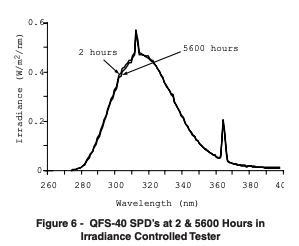
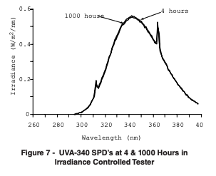
Figure 7 shows SPD’s of a set of UVA-340 lamps first measured at 4 hours and then aged 1000 hours and remeasured. Again, the spectral distribution is nearly identical.
Temperature
Fluorescent lamps are designed to operate most efficiently at 40° C. When operated at higher temperatures, light output declines. G53 devices typically operate at greater than 50° C. This means that fluorescent UV testers operating at a high black panel temperatures have lower irradiance than those operating at a cooler temperatures.
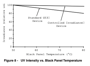
To help compensate for this drop in light output, some G53 devices cool the fluorescent lamps by blowing a stream of room air over the ends of the lamps. This helps offset the drop in irradiance at high chamber temperatures but does not completely eliminate it. The controlled irradiance tester maintains a constant irradiance by increasing the power to the lamps at higher chamber temperatures. Figure 8 shows the irradiance at various black panel temperatures for both the standard G53 and controlled irradiance tester.
Although the irradiance changes with chamber temperature it should not be considered a source of variability. This is because since tests run at two different temperature would not be expected to yield identical results anyway, it is not crucial that the irradiance be identical. On the other hand, it is advantageous for the irradiance remain constant when attempting to test for the effect different temperatures have on degradation.
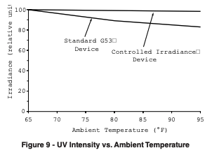
Ambient air temperature also has an effect on the irradiance level since it is used to cool the ends of the lamps. Obviously cool ambient air cools the lamps more effectively than warm ambient air and consequently, lamp output varies depending on ambient temperature. This is one reason that G53 specifies laboratory temperature limits. Figure 9 illustrates the effect ambient temperature has on standard G53 devices and how the automatic irradiance control system eliminates this source of variability on UV intensity.
Procedural Sources of Variability
While the above items are significant potential sources of variability in properly operated G53 devices, improper procedures (especially maintenance and calibration) can be equal or even more significant sources of variation. The effect of poor lamp maintenance on irradiance has already been discussed. Following are several other procedural sources of variability.
Temperature Calibration. The black panel thermometer frequently drifts over time and therefore should be regularly re-calibrated. In laboratories where maintenance of testers is poor, it is not un - common to find testers that are 5 ° C out of calibra - tion. In addition to the obvious differences in test reproducibility that temperature itself can cause, it also affects fluorescent lamp output as previously discussed. Consequently, apparatus that differ in black panel temperature will also differ in light out - put. The controlled irradiance system maintains the proper intensity, regardless of any errors in black panel temperature.
Lamp Fault. Variability can also be a result of something as simple as the lamps not lighting. This could be caused by a premature lamp failure, but more often than not, is because of a loose lamp connection. Routine monitoring will reveal such failures, but a significant amount of time can pass before the fault is discovered. When a lamp failure occurs in the automatic irradiance control system the sensor closest to the failed lamp detects the failure and an alarm is activated.
Lamp Cooling System. The purpose of the lamp cooling blowers is to help offset the drop in irradiance at high chamber temperatures. If the cooling blowers fail, the irradiance level will drop by as much as 20%. Therefore, regular inspection and maintenance is required to insure that the blowers are operating properly. With the controlled irradiance system, constant irradiance will be main - tained or an alarm will sound.
Test Specimen Location. The irradiance within the sample mounting area of fluorescent UV devices is not perfectly uniform. To minimize any effects from temperature or UV light variation, G53 requires that test samples be regularly rotated both vertically and horizontally. When test samples are rotated, they are exposed to an average irradiance and any effect from the non-uniform conditions is mitigated.
Laboratories, however, commonly fail to rotate samples on a regular basis. The consequences of not rotating samples vertically has been lessened with the irradiance control system. The two sensors on each side of the chamber, one on top and one on the bottom, and a modified chamber interior work together to distribute the light more uniformly. Figure 10 shows a simplified cross section of a standard G53 tester and figure 11 shows the modification. In the modified version, two light bars have been removed and the other two have been repositioned. A barrier has also been installed in the top center of the chamber.
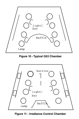
Figure 12 shows the vertical irradiance profile from the standard G53 device. There is a drop in intensity at the top and bottom of the sample mounting area and there is a peak just below the center of the sample plane. This peak is primarily the result of light coming from the lamps on the opposite side of the chamber.
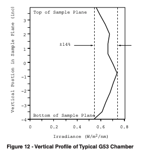
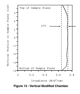
Figure 13 shows the vertical irradiance profile of the modified chamber. The chamber modifications alter where the light coming from the lamps on the opposite side of the chamber falls. The light is blocked in the middle where the intensity is high in the standard G53 chamber and allowed to pass through at the top and bottom where it is low. This modification improves the vertical uniformity from ±14% to ±7%. Although this is a significant improvement, top to bottom rotation is still recommended. Left to right rotation remains just as necessary with the standard G53 devices as with the controlled irradiance version.
Exposure Repeatability
The data presented thus far has shown that the automatic irradiance control system largely eliminates variations in UV intensity and therefore largely eliminates variations in test results. To test this hypothesis, a series of tests were conducted on a polystyrene reference material which appre - ciably yellows in a matter of days when exposed to UV. Three replicates were exposed for each test. The first three tests were done in the same tester using the same set of lamps but at different times and therefore different lamp ages (0, 1100, and 1240 hours). The fourth test was done on a different tester with different lamps (0 hours). UVB313 lamps were used for each test and the tests were all run at 50°C. Delta b* readings are shown in figure 14 for each of the test samples after 51 hours exposure.
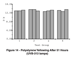
The total variation in delta b for these 12 test specimens was ±4% and takes into account; different lots of lamps, different lamp ages, different test chambers, and a 5°F difference in ambient temperature.
High Irradiance
In addition to reducing the sources of variability in G53 tests, the programmable, automatic irradiance control system allows the operator to choose a higher than standard level of irradiance for UV exposure tests. For many materials, this results in faster degradation and therefore shorter test times. Figure 15 and 16 show UVA-340 and UVB-313 lamps at various irradiance levels, compared to sunlight.
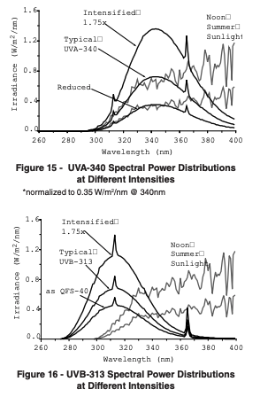
The recommended maximum increase over “normal” irradiance is 75%. The lamps are typically capable of higher intensity levels at full power but it is not recommended that tests be run at levels higher than 1.75x normal. This is because there must be some excess power available to maintain the desired set point and account for such things as lamp aging and other factors which reduce the maximum irradiance potential. It should be noted that lamps operated at higher than normal irradiance will have a proportionally shorter useful life span.
In addition to higher intensity, lamp output can also be reduced. With the UVA-340 lamp, this could be done to match “average optimum” conditions. With the UVB-313 lamp, output can be reduced to match the FS-40 lamp.
High Irradiance Exposure Results
There is currently a high level of interest in using high irradiance exposures as a method of accelerating laboratory weathering tests. To determine the effect of increased irradiance on degradation rates, a series of materials were exposed in a G53 tester with automatic irradiance control at normal and high irradiance. The exposure conditions were, UVA-340 lamps, light only (100% UV, no moisture, no dark time), 50o C. The irradiance levels were 0.83 and 1.35 W/m2 / nm @ 340 nm. The results are shown in Figures 17 through 23.
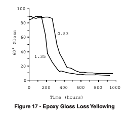
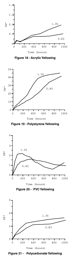
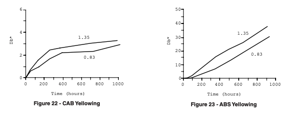
For these particular materials, increased irradiance resulted in an increase in the rate of degradation. The increase in the rate of degradation, however, was not the same for all materials. It should also be noted that these exposures did not include moisture or dark time. Therefore, moisture effects and/or any darktime-degradation effects cannot be evaluated. For materials which experience significant degradation due to moisture, there may be little or no increase in degradation at high irradiance. Furthermore, experience indicates that irradiance, moisture, dark time, and temperature frequently have a synergistic effect. Thus, using high irradiance to reduce test time could have a detrimental effect on the correlation between laboratory and outdoor results.
Conclusions
Consistent and repeatable test results are necessary to allow the direct comparison of materials that have been tested at different times and places. Only if the exposure environment is controlled, can differences in test results be attributed to differences in material durability, rather than differences in test conditions. Further, specification tests performed in multiple laboratories, or throughout an industry, are meaningful only if all labs can achieve consistent results.
An automatic irradiance control system incorporating four sensors in a feedback loop has been described for use in fluorescent UV weathering testers. Measurement and exposure data show that the system greatly reduces variations in UV intensity due to lamp manufacturing, lamp aging, temperature, and poor maintenance. The irradiance range typical of standard G53 devices is reduced to a quantifiable, repeatable number expressed in W/m2 /nm. The system maintains a precise UV intensity level throughout an exposure test. The uniformity of the UV light throughout the test sample mounting region is also improved by modifications to the interior of the chamber.
With the programmable, irradiance control system, the operator can choose from a range of irradiance levels. Of particular interest, operators can increase the irradiance 75% over that of a standard G53 device. Exposure data from a variety of materials indicates that materials exposed at high irradiance levels degrade faster. Within limitations, test times can be reduced.
Acknowledgment
The authors would like to recognize Sandra Kalmbach for her assistance in data collection and organization.